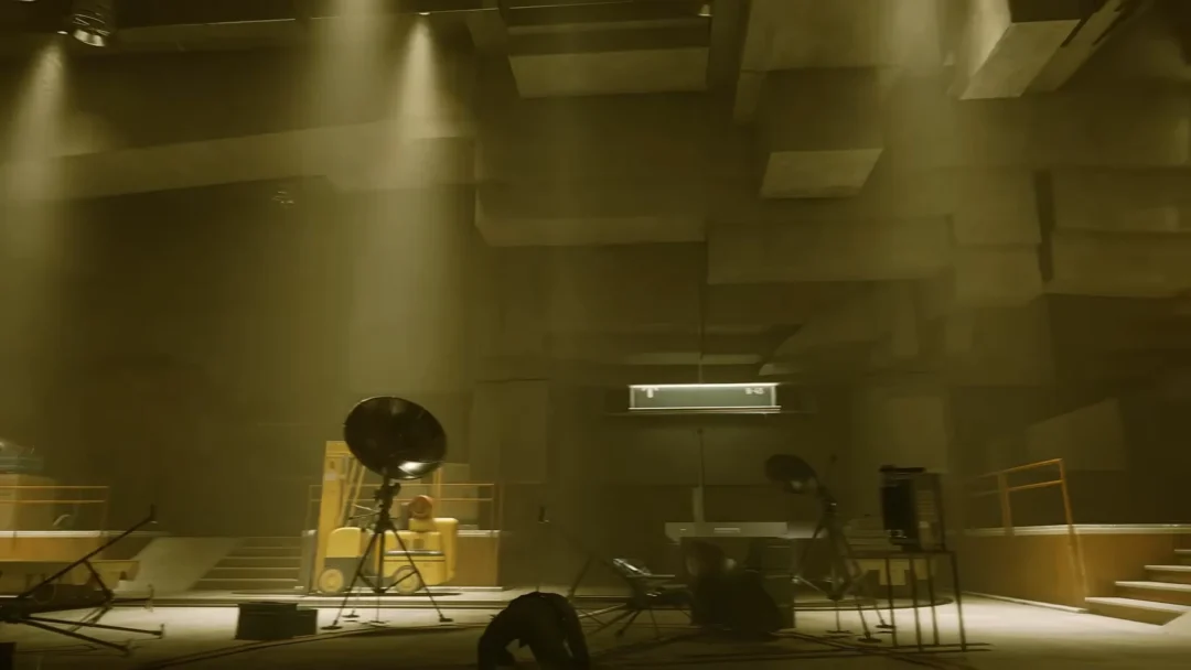

The SWDP Control Room in Silent Hill: Townfall is one of the game’s longer multi-part puzzles, mixing console commands, camera lookups, a floppy-disk pipe alignment, and a final clamp release panel. The whole sequence runs on one simple rule at the console, and everything else is about finding the right three-digit codes and turning the right wheels in the right order.
Quick answer: Enter each console command as [Command] + [Equipment] + [3-digit ID] + Enter, complete the AUX room pipe alignment and manual valves, configure the clamp panel, then turn the green-lit emergency release wheel on the lower floor.
How the SWDP console works
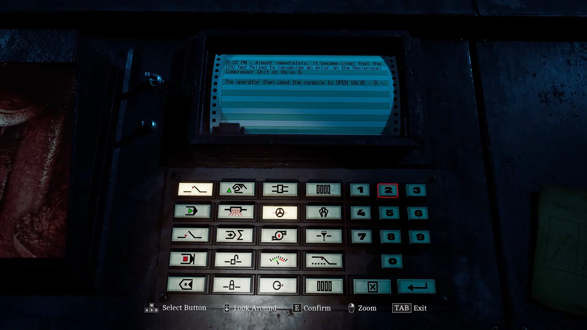
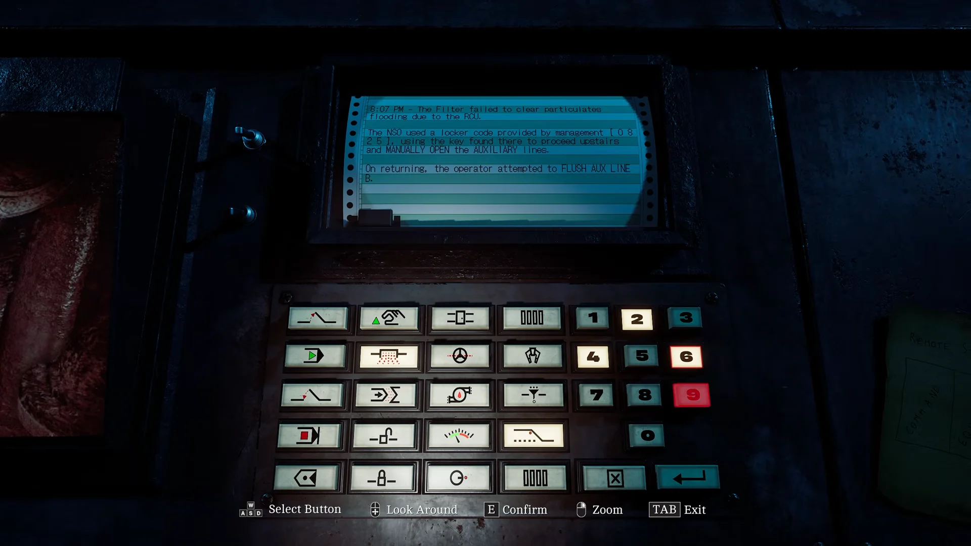
Every command at the main console follows the same three-part structure. You pick a command word, pick the equipment it applies to, type the matching three-digit ID code, then confirm with the green Enter button. The Remote Systems Control note on the desk lists the command order and the auxiliary line codes, so keep it handy.
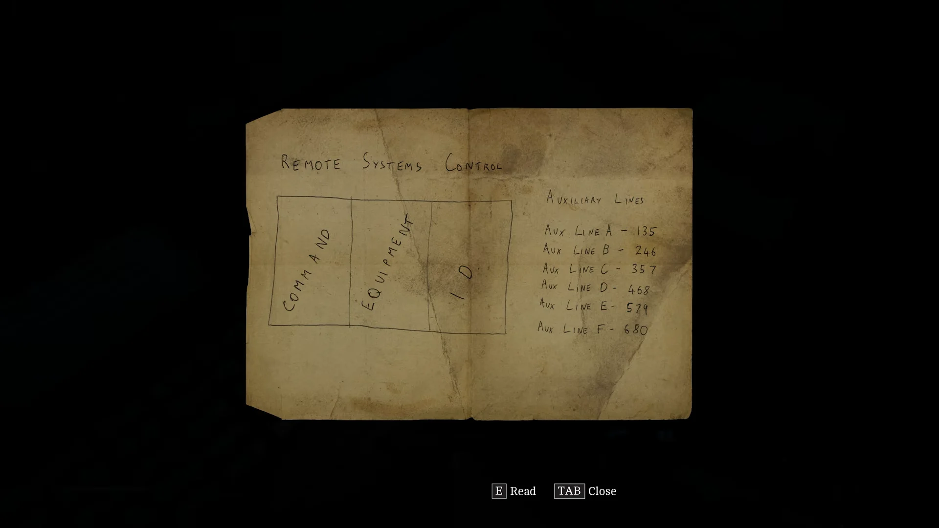
Before entering anything, flip the main console power switch on. The printer log prints each task in order, and the security cameras around the facility show the three-digit ID stamped on each piece of equipment. The auxiliary line codes come from the desk note instead of a camera.
Here are the six console entries you’ll make across the puzzle, along with where each ID comes from.
| Command | Equipment | ID code | Where the ID is found |
|---|---|---|---|
| Open | Valve | 254 | CAM 005 (Valves A–C) |
| Start | Filter | 103 | CAM 000 (Filter Unit floor) |
| Flush | Aux Line | 246 | Desk note (Aux Line B) |
| Stop | Regulator | 781 | CAM 002 (Regulator Systems) |
| Unlock | Door | 592 | CAM 004 (above the Valve F door) |
The command, equipment, and ID buttons sit in a grid. Open is row 1 / column 1, Start is row 2 / column 1, Flush is row 2 / column 2, Stop is row 4 / column 1, and Unlock is row 4 / column 2.
Open Valve B and start Filter A
The first two printer tasks are pure console work. Both codes come from the security cameras, so check the feeds before typing.
Get the AUX Key and align the auxiliary pipes
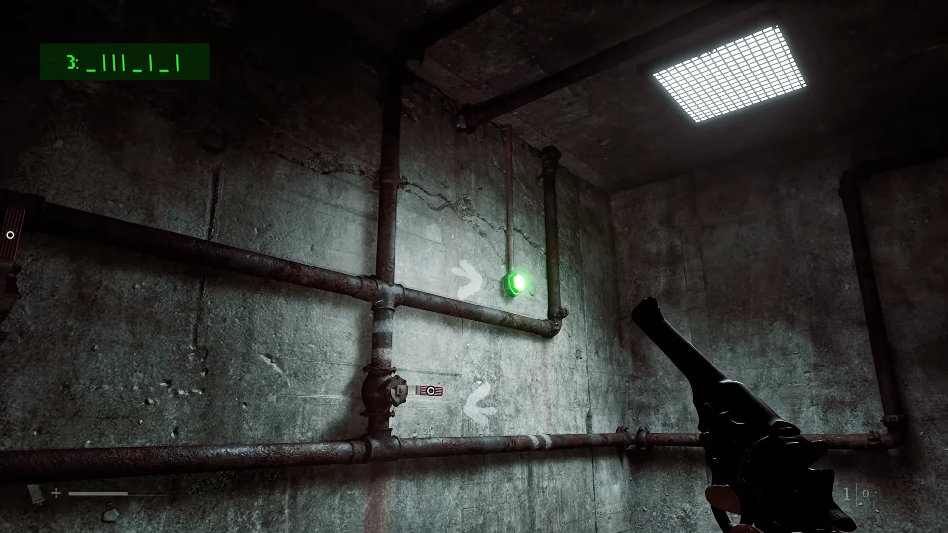
The console can’t open the auxiliary lines on its own. You’ll head down to floor G to do it by hand, using a floppy disk to read the correct valve pattern.
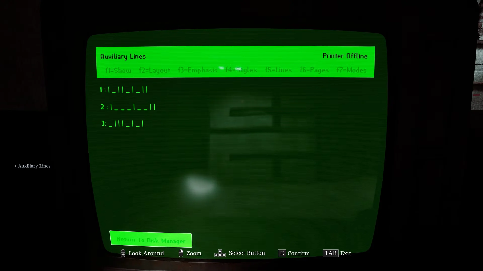
_) means the valve should be horizontal, and a vertical bar (|) means it should be vertical. The wall notches (1, 2, or 3) and painted arrows tell you which line each valve belongs to and where to start.- Line 3 (top row, beginning near the entrance): Set the valves by position: 1—Horizontal; 2—Vertical; 3—Vertical; 4—Vertical; 5—Horizontal; 6—Vertical; 7—Horizontal; 8—Vertical.
- Line 2 (middle row, beginning on the rear wall across from the entrance): Set the valves by position: 1—Vertical; 2—Horizontal; 3—Horizontal; 4—Horizontal; 5—Vertical; 6—Horizontal; 7—Horizontal; 8—Vertical; 9—Vertical.
- Line 1 (bottom row, beginning on the rear wall): Set the valves by position: 1—Vertical; 2—Horizontal; 3—Vertical; 4—Vertical; 5—Horizontal; 6—Vertical; 7—Horizontal; 8—Vertical; 9—Vertical.
Flush AUX Line B, stop the regulator, unlock the Valve F door
With the pipes aligned, return to the control room console for the next three printer tasks.
Manually turn Valve F
Unlocking the door opens the path to a valve you have to turn by hand. Leave the control room and take the stairs down, passing the creature that stalks the hallway. Follow the corridor to Valve F and turn the large wheel valve. That clears the way for the clamp release stage.
Configure the Clamp Release panel
Back in the control room, pick up the Clamp Release Procedure printout from the printer on the far-left desk, then step over to the clamp control console on the opposite wall (model no. 920CEG). Set every control exactly as follows.
- Pressure Control slider to SET.
- Set the SELF and ALL Notify switches both to ON.
- Move both dials, Tension (L) and Tension (R), to INTERMEDIATE.
- Run Off switch to DISENGAGED.
- Intubate Flow slider to NONE.
- Enter clamp ID D71 on the keypad.
- Report toggles 01, 03, and 06 flipped to ON (down).
- Choose B for Battery One, then activate Battery Two and wait for the READY light to turn green.
The tension dials specifically follow the 920CEG model number, which calls for both left and right set to INTERMEDIATE. Once the READY light is green, press the flashing green RELEASE button.
Turn the final release wheel to finish
Press RELEASE to arm the final valve. Go down to the lower observation floor and turn the emergency release wheel valve, which is now glowing green. Turning it restores facility operations and completes the puzzle, allowing you to proceed beyond the SWDP Control Room.