
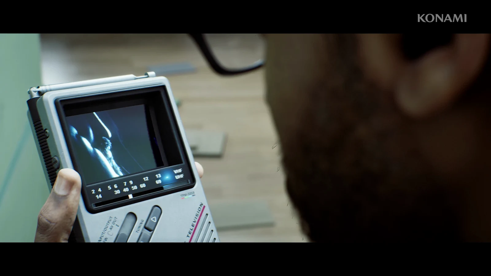
At the Control Room, the Remote Systems Control document is added to your inventory along with one opaque instruction: recreate what the CCTV recorded. Nothing else is available in the room. Solve it by repeating two actions—read a device ID from a security camera, then submit the corresponding command at the console—until every valve, filter, and regulator has been handled.
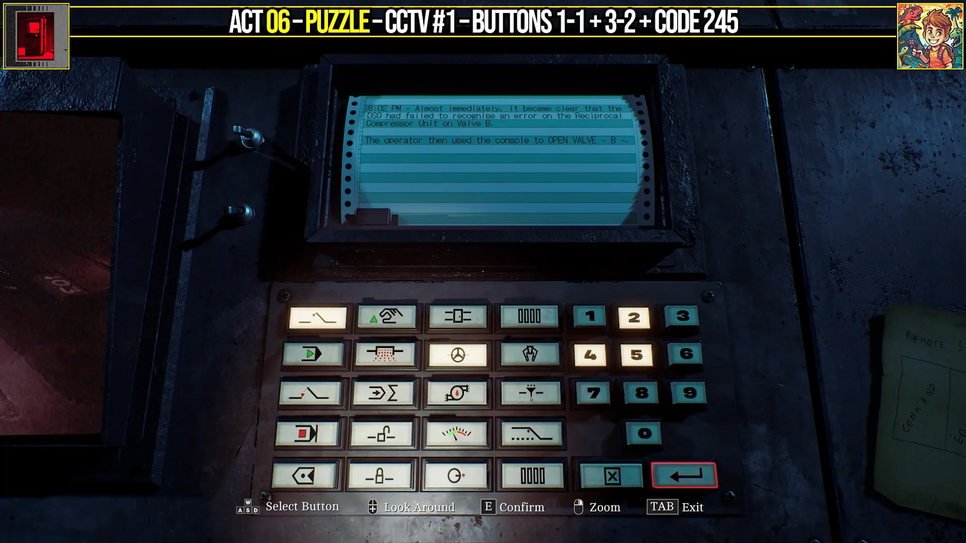
Quick answer: Read each device ID from the CCTV cameras, then enter its Command and Equipment symbols on the console — Valve B (254), Filter A (103), Aux Line B (246), Regulator (178), and the Valve F door (592).
How the console reads commands
The Remote Systems Control document explains that each entry uses three sections. Use the first pair of button columns to select the Command, and the next pair to select the Equipment. Enter the ID of the target device in the number field.
IDs come from the equipment itself, viewed through the security cameras, or from the note posted beside the console; do not try to work them out. Select the Command and Equipment, enter the ID, and press Enter to submit it. Leave the “Aux Line B” code on the document alone until that step arrives.
Console command reference
Here is every command coordinate alongside the ID it needs. Enter them in the order shown further down, since the tasks depend on one another.
| Task | Command | Equipment | ID |
|---|---|---|---|
| Open Valve B | Col 1, Row 1 | Col 3, Row 2 | 254 |
| Start Filter A | Col 1, Row 2 | Col 4, Row 3 | 103 |
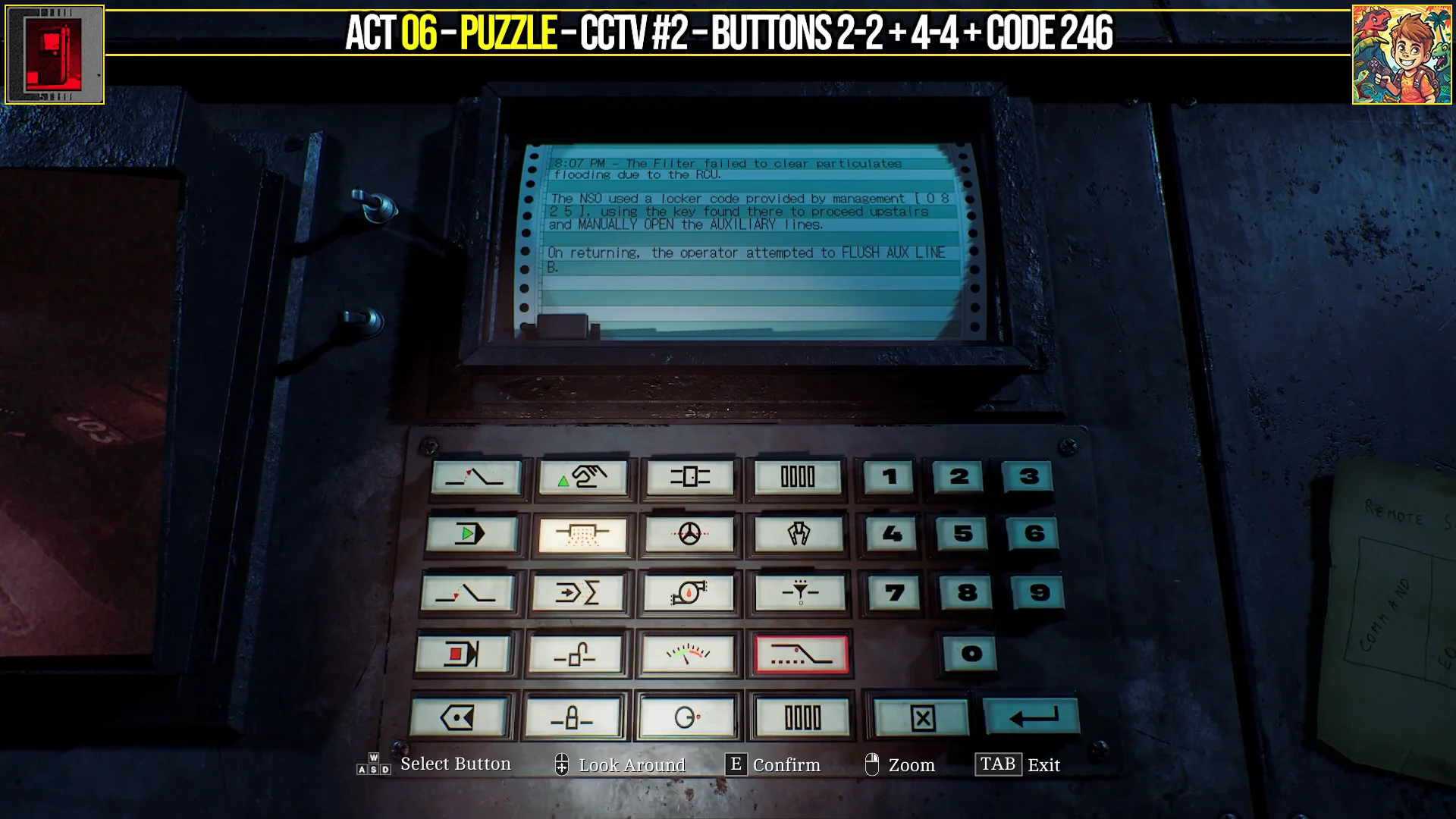
| Flush Aux Line B | Col 2, Row 2 | Col 4, Row 4 | 246 |
| Stop the Regulator | Col 1, Row 4 | Col 3, Row 4 | 178 |
| Unlock Valve F door | Col 2, Row 4 | Col 3, Row 1 | 592 |
Open Valve B and start Filter A
Fix the auxiliary lines manually
The next objective can’t be done from the console. You have to open the auxiliary lines by hand, which means leaving the Control Room for a short detour.
| Line | Start / direction | Switch order |
|---|---|---|
| Line 1 (one stripe, 9 switches) | Right side, right to left | Up, Down, Up, Up, Down, Up, Down, Up, Up |
| Line 2 (two stripes, 9 switches) | Right side, right to left | Up, Down, Down, Down, Up, Down, Down, Up, Up |
| Line 3 (three stripes, 8 switches) | Left side, left to right | Down, Up, Up, Up, Down, Up, Down, Up |
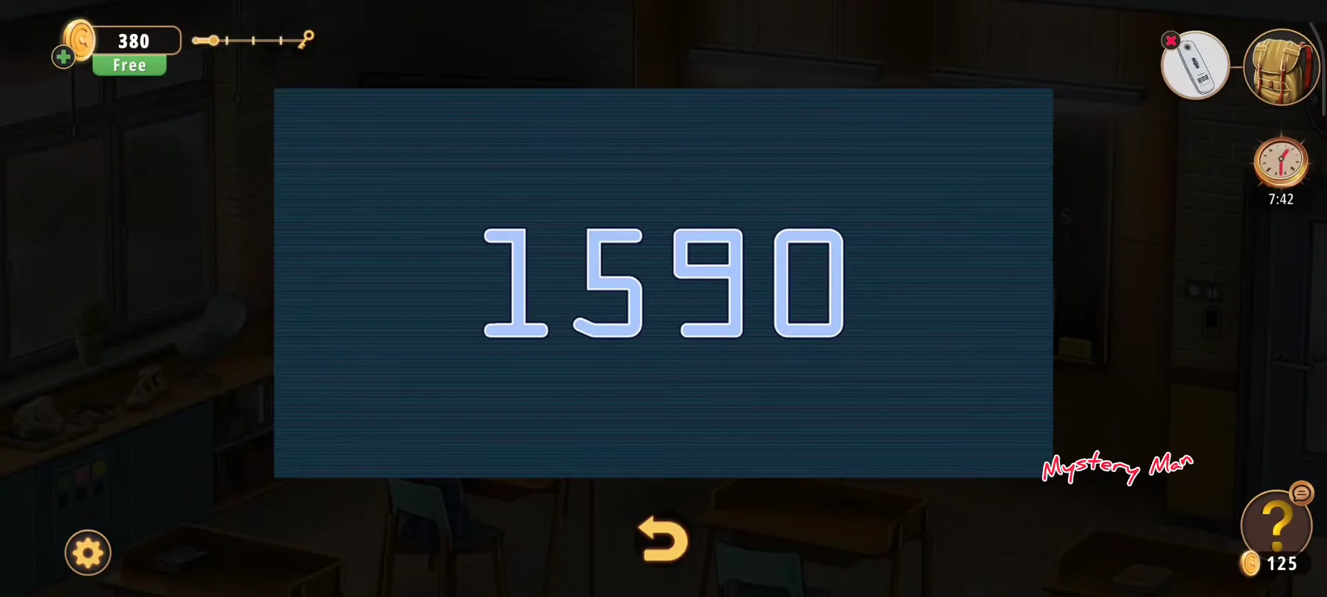
When all three status lights turn green, the auxiliary lines are open. Head back to the Control Room.
Once inside the Control Room, secure its door so roaming enemies cannot get to you while you operate the console.
Flush Aux Line B, stop the Regulator, and unlock Valve F
Turn the Valve F wheel and confirm completion
Once the door is open, exit the Control Room and follow the downstairs route along the left side of the ground floor. Valve F is underneath; turn its red wheel to remove the warning from the controls.
The sequence has ended when Valve F no longer shows the warning. Go back upstairs and lock the doors again; the printer then produces a new document called the Clamp Release Procedure. That printout starts the next puzzle in the chain.