
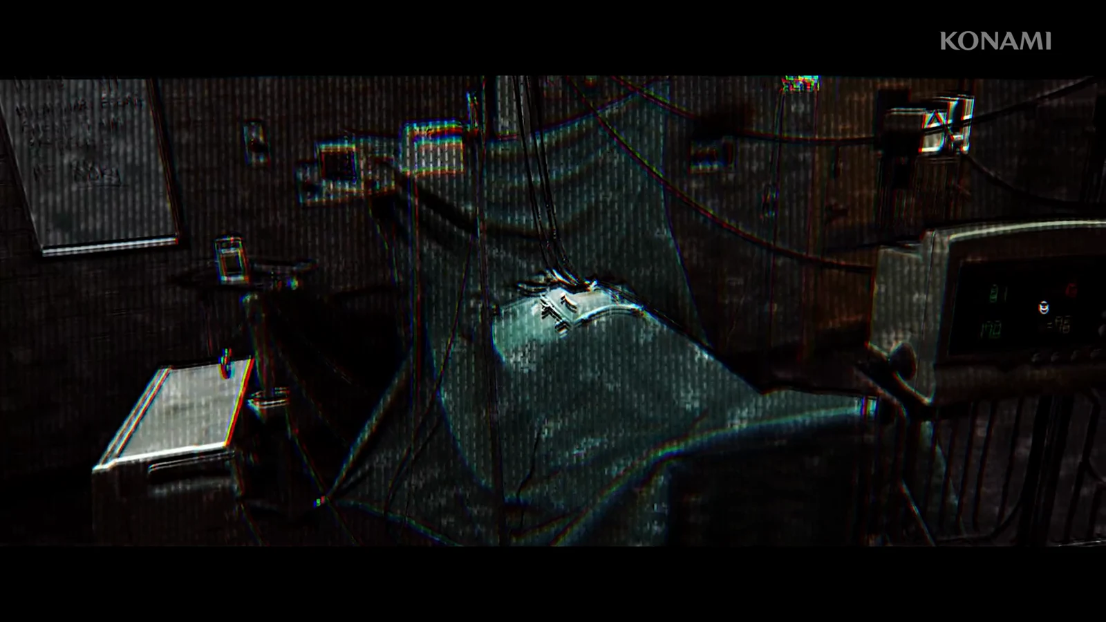
The command console in the CCTV room is the spine of Part 6 in Silent Hill Townfall, and it stretches across the whole SWDP – Different area. A voice on the intercom asks Simon to retrace the events of “that night,” and each printed message on the console tells you the exact action the original operator took. Your job is to repeat those actions in order, mixing keypad codes with real valves you have to turn by hand elsewhere in the facility.
Quick answer: Enter each logged action on the console in Command → Equipment → ID order, using the camera feeds to read each ID code, then complete the physical valve tasks between entries and finish at the clamp release panel.
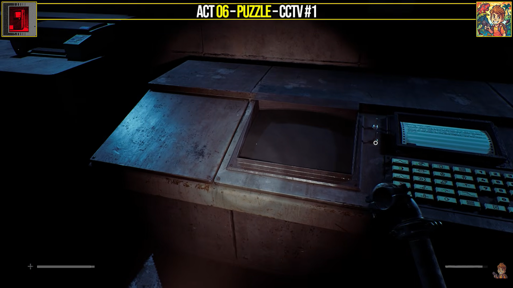
How the command console reads your inputs
Set both switches on the machine to power up the CCTV system and console. The console is positioned to the camera monitor’s right and resembles a fax reader, with an engineering-symbol keypad. For each entry, follow the order on the Remote Systems Control Note: press Command, then Equipment, enter the numeric ID, and finish by pressing Enter.
You read most ID numbers off the camera feeds. Switch between the numbered cameras on the CCTV monitor and zoom in on the equipment named in each message to find the code painted on it. If you press the wrong combination, the console displays a failure message and resets, so a mistake costs nothing except time.
The Remote Systems Control Note provides one ID outright: Aux Line B – 246. Before you begin, collect the Lockbox Key items and med kit, and locate the save phone. Lock both doors in the room to stay safe while you work.
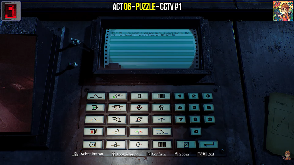
All console codes and camera locations
| Action | Where to read the code | Code |
|---|---|---|
| Open Valve B | Cam ID 5 (Valves A–C) | 254 |
| Start Filter A | Cam ID 0 (Filter Unit) | 103 |
| Flush Aux Line B | Remote Systems Control Note | 246 |
| Stop the Regulator | Cam ID 2 (Regulator Systems) | 781 |
| Unlock Valve F door | Cam ID 4 (ID above the door) | 592 |
| AUX Key locker | Given in Message #3 | 0825 |
| Clamp connection | Stencilled on clamp arms | D71 |
Console sequence, message by message
Work through the messages in the order they appear. Each new message only shows up once the previous action succeeds, so a correct entry is its own confirmation that you can move on.
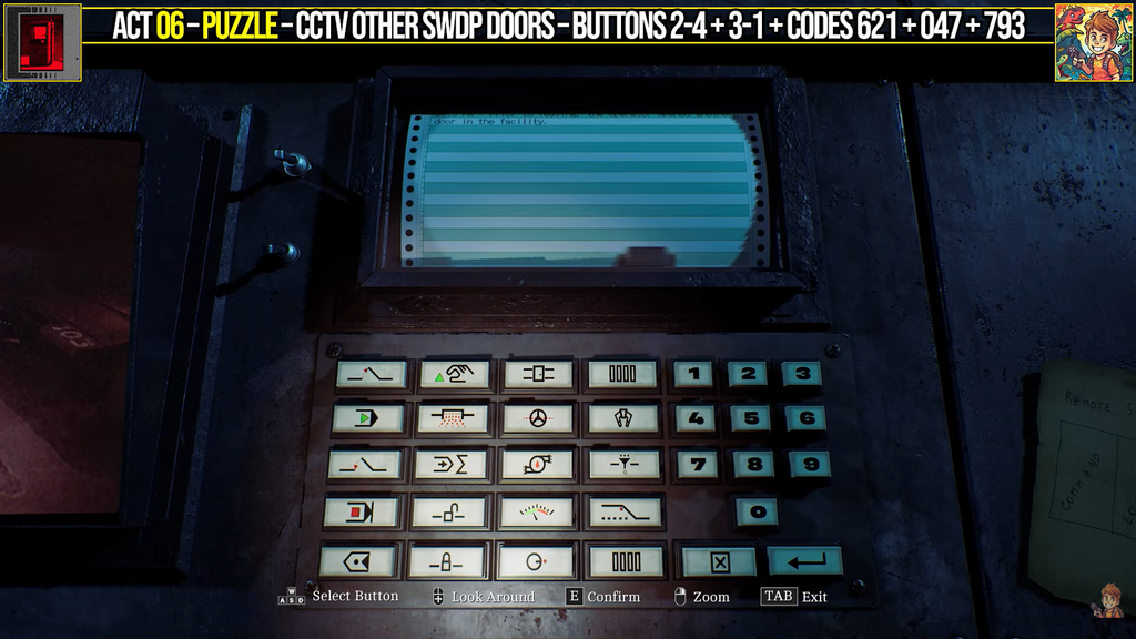
Clamp release panel settings
Opening Valve F sets off the reaction that wraps up the console section. The final message directs you to the Clamp Release Module on the panel across from the console. At the printer to the command console’s left, take the Clamp Release Procedure document; then use the clamp controls and enter these settings.
- Set Pressure Control to SET.
- Switch the Self/All Notifiers ON.
- Panel Model is 920CEG, so set Tension and Balance to INT / INT.
- Set Run Off to DISENGAGED.
- Set Intubate Flow to NONE.
- Input the clamp connection ID D71, stencilled on the clamp arms.
Next, toggle the report switches to match the clamp letter configuration. The letter is D, so turn on the first, third, and final switches. Adjust the power configuration until the battery status light comes on, with Battery 1 set to B and Battery 2 set to C. With every control correct, the release indicator flashes — press it to release the clamps.
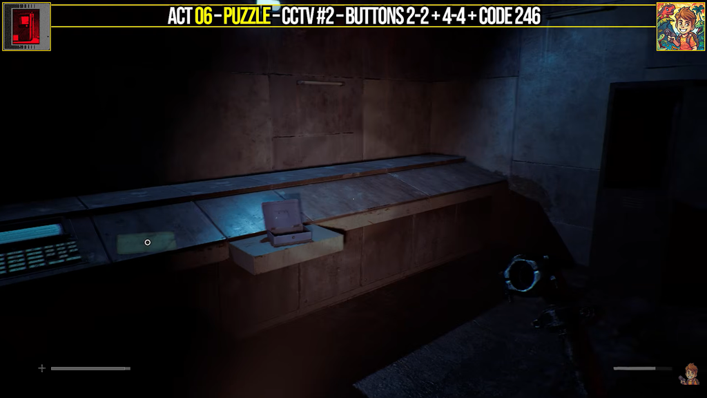
How to confirm the puzzle is complete
You know the console section worked when each entry advances to a new message instead of showing the failure notice and resetting. Once the clamps release, a large container lowers into the middle of the CCTV room. That drop is the sign the whole sequence is finished, and you can leave the room to continue Part 6.